


For the overall surveying industry, including powerline infrastructure inspection - Aerial Unmanned Vehicle (UAV) usage brings vital time and money saving and decreases exposure of staff to dangerous environments.
UgCS provides convenient tools to acquire data of any powerline inspection type to detect:
- Concrete basement defects
- Insulator overheating
- Wire overheating
- Wire breaks
- Tower mechanical defects
- Corridor inspection to detect unauthorized objects or vegetation in secured territory
- Wire sag estimation
- Corona detection*.
In the following sections, we will explain specifics on how to perform a powerline inspection using the functionality and tools of UgCS. The process consist of the following steps:
Import inspection area coordinates
Defining the geography of inspection is the essential thing for mission planning. Typically customers ordering an inspection provide coordinates of the inspection area to UAV service provider in some common format like CSV or KML. To import a linear object from CSV/KML format files into UgCS:
- In mission editor click “Add new route”
- Select “Import” in file option and browse the needed CSV / KML file*
- Press "Next" and continue with UgCS standard route creation procedure (see chapter Plan mission).
*Please note that KML/CSV import is available for UgCS PRO, UgCS EXPERT, UgCS ENTERPRISE users.

Plan mission
Choosing the equipment: drone and payload
For UAV survey missions the choice lies between fix wing or copter drones. UgCS supports both UAVs types, therefore the choice of equipment, depends on the type of inspection. The most obvious pros and cons of fixed-wing vs. copter drones:
Also for the sensors, the best way to choose the right one is to determine the needed result.
A brief summary of EO, IR, UV cameras or LIDAR application, according to powerline inspection type:


(image courtesy © Riegl Laser Measurement Systems)
Planning the route
Having geography data and suitable equipment for the inspection, the route can be planned in UgCS. There are several important features that may greatly simplify planning.
Working with multiple segments/waypoints simultaneously
In UgCS it is possible to select multiple waypoints at the same time. To select all waypoints click CTRL (cmd)+A or while holding CTRL (cms) select individual waypoints. It will be possible to bulk edit:
- speed;
- altitude;
- turn type;
- add/remove actions (e.g. camera by time or servo by time).

It is also possible to move and rotate selected waypoints at once with the handle.

Usually, for inspection, the GSD is set relative to the ground. For some powerline inspections, it is needed to set GSD relative to the wire. In this case, the inspection's latitude should be increased to tower height.
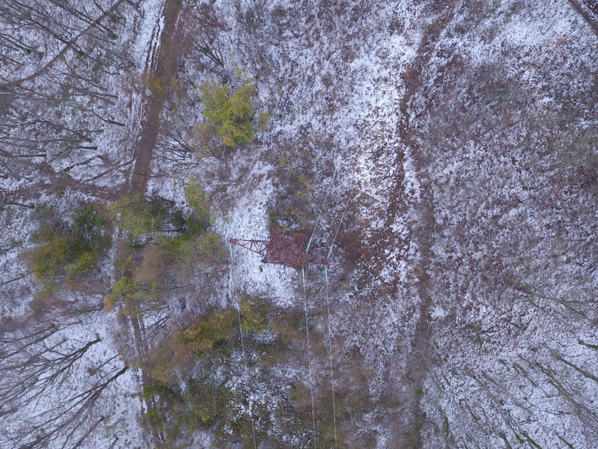
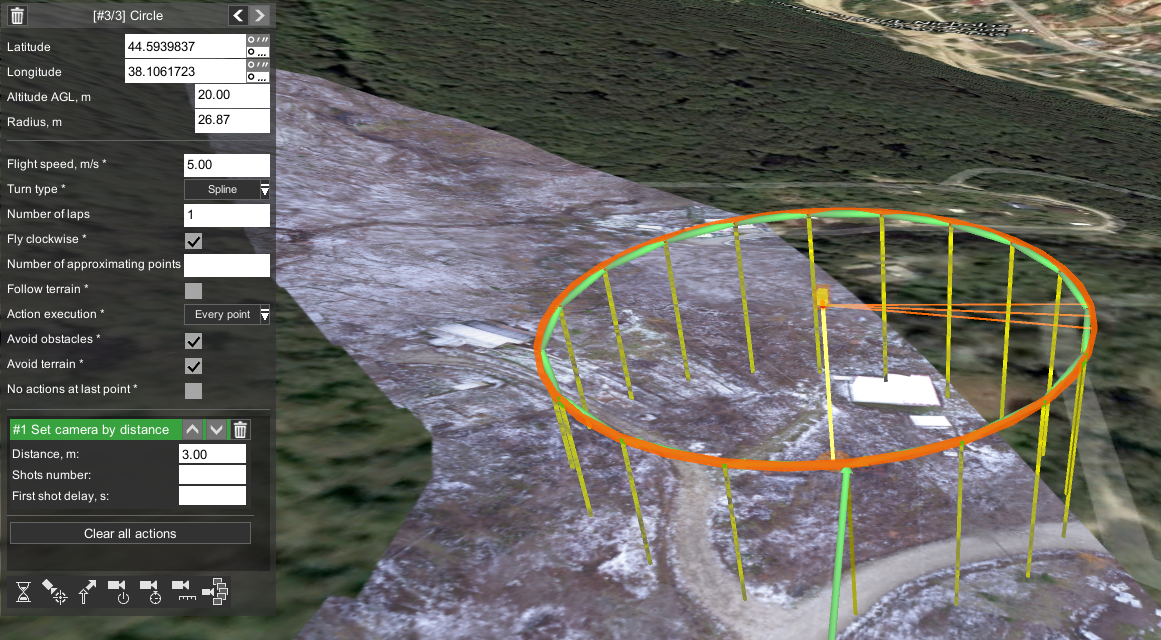
Using circular segments
To inspect the tower from a different point of views around it, the UgCS Circle tool should be used. UgCS will direct the drone to look to the center of circle route.
Control gimbal to capture nadir or oblique images
Depending on autopilot support, UgCS support actions to control camera attitude along the route. Therefore it is possible to set the camera to nadir or oblique position, to take images according to desired inspection's goal.

Control video recording setting along the route
UgCS enables to control camera's recording mode - e.g. it is possible to set, that video recording starts just before the powerline's tower and stops right after the drone has passed the tower. This is useful to reduce video length - simplifying acquired data analysis - having videos with only useful data.
To set up video recording (for integrated cameras like DJI's) only for specific part of the route:
- insert additional points before and after the tower
- for the point before tower add "Set camera mode" action to "start recording"
- for the point set after the tower - add "Set camera mode" action to "stop recording"

Route planning in complex elevations
For inspection flights at a complex landscape, it is mandatory to check the whole route according to landscape profile. UgCS provides several means to create a safer flight:
- UgCS elevation database - the data itself is an SRTM with 90m precision
- UgCS PRO / UgCS EXPERT / UgCS ENTERPRISE users have the option to import any elevation data (DEM) for the inspection region
- UgCS route planner always tries to calculate actual flight path in a safe distance from digital elevation model (DEM)
- The Elevation profile view displays the path and respective elevation along it.

Deploy ground control points
Ground control points have to be used to create Survey-Grade result. For a map with approximate precision, it is sufficient to rely just on RTK GPS and capabilities of data processing software.
Fly the inspection mission
If the mission is planned carefully, flying it is the most straightforward step. We will not go into detail in this topic, as flying the mission depends on chosen UAV and equipment (for detailed information, please refer to equipment’s and UgCS documentation).
Important issues before flying:
- In most countries, there are strict regulations for UAV usage. Always comply with the regulations! Usually, these rules can be found on the website of local aviation authority.
- In some countries, special permission for any kind of aerial photo/video shooting is needed. Please check local regulations.
- In most cases missions are planned before arriving in flying location (e.g., in office, at home) using satellite imaginary from Google maps, Bing, etc. Before flying always check actual circumstances at the location. There could be a need to adjust take-off/landing points, for example, to avoid tall obstacles (e.g., trees, masts, powerlines) in the inspection area.
Process the acquired data
Image geotagging
Image geotagging is optional if ground control points were used, but almost any data processing software will require less time to process geotagged images.
Some latest and professional drones with an integrated camera can geotag images automatically during flight, in other cases, images can be geotagged in UgCS after the flight.
Very important: UgCS uses telemetry log from the drone, that is received via a radio channel, to extract drone’s position for certain moment (when pictures were taken). To geotag pictures using UgCS assure robust telemetry reception during flight.
For detailed information how to geotag images using UgCS refer to UgCS User Manual.
Image processing
Starting UgCS PRO version 2.12 UgCS MAPPER beta is launched - a desktop geo-referenced image processing software, to create 2D maps in-field, requiring no internet connection. In-field assembled map provides certainty for UAV surveyors that acquired images quality and density is sufficient. This information is crucial to decide whether the flight should be repeated before leaving the inspection area.
To make more detailed analysis and 3D models from acquired images, third-party software can be used.
Import map into UgCS for repeated inspections (optional)
Powerline inspections usually have to be repeated regularly. Data acquired during the first inspection flight can be imported into UgCS as map layer (GeoTiff file) and used for more precise mission planning. Detailed instructions how to use Map overlay can be found in UgCS User Manual.
*Corona detection with UF camera is still a very specific topic for UAV. More detailed information on this topic can be found: http://www.ofilsystems.com/articles/index.html